| Note: This article is in collaboration with Teh Su Yang. View his Linkedin profile here! |
Building your own solar powered watering system has never been easier. With the right tools, and a little bit of technical know-how, you’ll have one up and running in your garden in no time!
This article records my effort to create an automated plant watering system together with an auto fishpond water refill system using Home Assistant and ESPHome using NodeMCU.
What software do you need to build your own solar powered watering system?
Home Assistant! It is a free and open-source software for home automation that is designed to be the central control system for smart home devices with focus on local control and privacy. This open source application enables the DIY smart home enthusiasts to create and customise their own ideal smart home.
What you need to build your own solar powered watering system?
You need 9 items before you can commence your quest in building your own solar powered watering system! All of them are available on Shopee / Lazada. The components used in this project are:
1. Raspberry Pi 4 (4GB RAM)
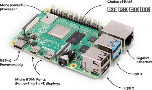
Shopee: Link for Raspberry Pi 4
2. NodeMCU V3

Shopee: Link for Node MCU V3
3. Solar Panel
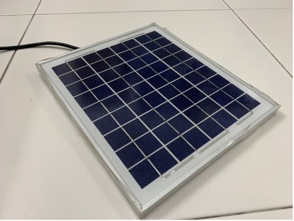
Shopee: Link for Solar Panel
4. PVM Solar Charge Controller

Shopee: Link for PVM Solar Charge Controller
5. Varta 12V 50Ah Lead-Acid Battery
Shopee: Link for Varta 12V 50Ah Lead-Acid Battery
6. Junction Box
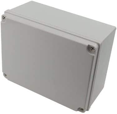
Shopee: Link for Junction Box
7. 12V DC Pump
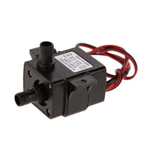
Shopee: Link for 12V DC Pump
8. 12V Solenoid Control Valve
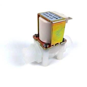
Shopee: Link for 12V Solenoid Control Valve
9. Barrel Connectors
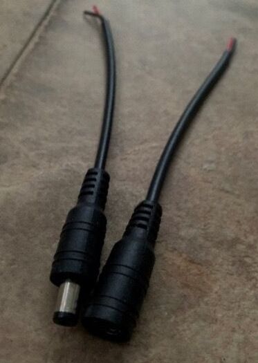
Shopee: Link for Barrel Connectors
4 steps guide to build your own solar powered watering system
Once you’ve obtained the necessary parts, you can start putting the pieces together to build your own solar powered watering system.
Step 1: Installing Home Assistant into Raspberry Pi
The Raspberry Pi acts as the hub to connect and integrate all the smart devices together. Follow the installation procedure here. The supported raspberry models so far are Raspberry 3 model b+ and Raspberry Pi 4 onwards.
Step 2: Connect the NodeMCU to Raspberry Pi
- Connect the NodeMCU to the Raspberry Pi through the USB port on the Raspberry Pi.
- Go to the Home Assistant dashboard, go to Configuration >> Add-ons, Backups & Supervisor >> ADD-ON STORE, on the search bar type ESPHome, install the add-on, turn on Watchdog and Show in sidebar, and click START.
- From the sidebar click ESPHome. At the bottom right corner click NEW DEVICE >> CONTINUE. Enter your desired name for the NodeMCU and click NEXT, Select Pick specific board, choose NodeMCU, click NEXT. A new tab with should appear at the background and a pop up of “Configuration created!” should appear as well. Click SKIP. Then install through the “Plug into the computer running ESPHome Dashboard. Select the usb port and it will start the installation.
- After the installation is finished, the NodeMCU will be connected to the Wi-Fi and ready to be used.
Step 3: Hardware & Electronic Setup
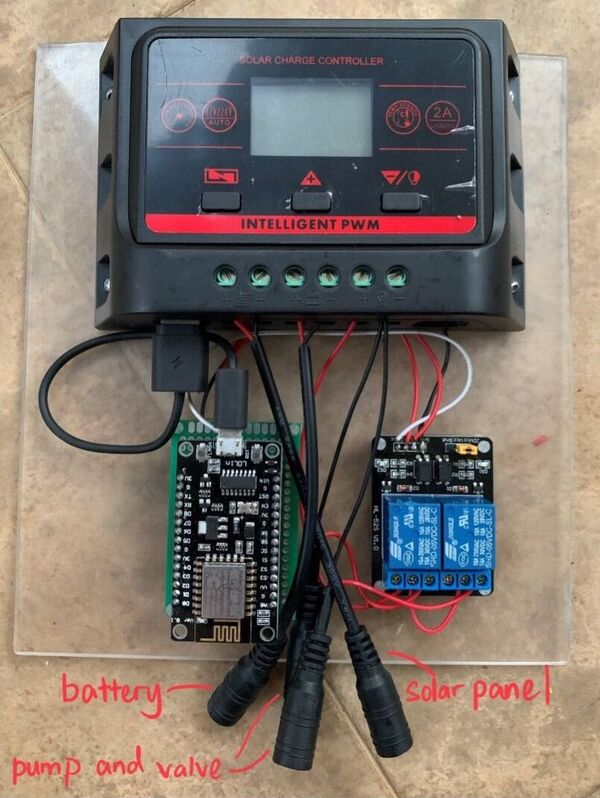
Next step is to wire all the components including the solar panel, solar charge controller, battery, 2-channel relay, pump, control valve and the NodeMCU together. Here’s the wiring diagram of the system:
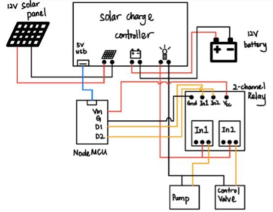
To make it modular, I mounted them on an acrylic board and installed the barrel connectors so that I can easily disconnect the cables if necessary.
Step 4: Configure the NodeMCU
Now that the connection is all done, it is time to configure the NodeMCU to execute the system based on our requirement.
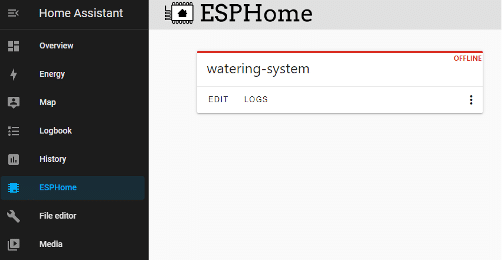
First go to the home assistant dashboard. Access ESPHome from the left sidebar. Click Edit.
This is the configuration file for the NodeMCU, before uploading the the board there are a few lines of code we need to add to this file.
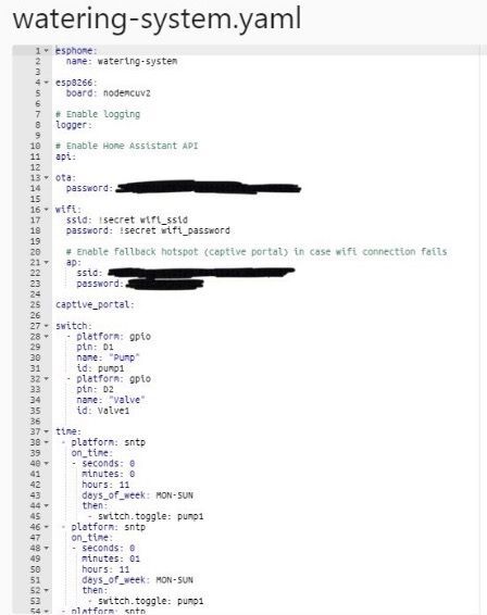
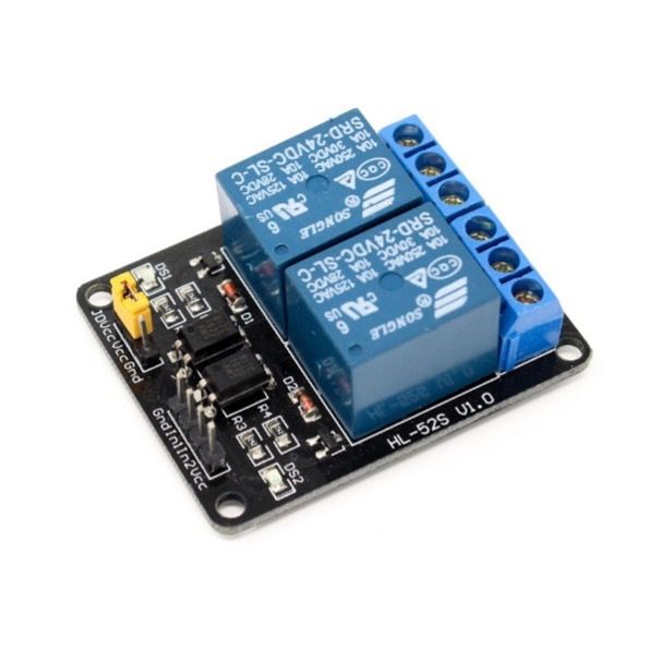
First is to let the board know that D1 and D2 pins will be used as switch to control the 2-channel relay to the pump and control valve. You can put any name and id that you want. Official documentation can be found here.
switch:
  - platform: gpio
    pin: D1
    name: "Pump"
    id: pump1
  - platform: gpio
    pin: D2
    name: "Valve"
id: Valve1
Secondly is to put the timers to automatically turn on and off the pump and control valve at the certain time of the day.
time:
 - platform: sntp
   on time:
   - seconds: 0
     minutes: 0
     hours: 11
     days of week: MON-SUN
     then:
      - switch.toggle: pump1
 - platform: sntp
   on time:
   - seconds: 0
     minutes: 01
     hours: 11
     days of week: MON-SUN
     then:
      - switch.toggle: pump1
For this specific configuration, I set a timer to turn on the water pump at 11.00.00 am and turn it off one minute later which is 11.01.00am, every Monday to Sunday. Note that the pump1 at the switch.toggle: is the id of the pump when setting up the gpio switch. For more information, please take a look at the documentation from the official website here.
Once everything is has been set up, click install and it will install wirelessly. It will take a few minutes to upload the code. Once the installation is complete, close the install tab and the system is good to go.
A little note here – these days there are many DIYs made possible by the easy availability of hardware as well as the codes. This is just a small attempt to get a working system for the home without having to spend too much.
Check out also: